01
YELLOW FILTER REQUIREMENTS FOR PHOTORESIST PROCESSING
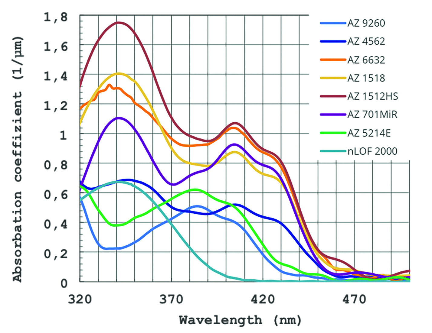
SPECTRAL SENSITIVITY OF PHOTORESISTS
The spectral sensitivity of common g-, h-, and i-line broadband photoresists ranges from the near UV to the short wave visible part of the spectrum in the range of 320-470 nm. The g-line absorption maximum at 435 nm wavelength is centered in the blue part of the spectrum and drops towards longer wavelengths without sharp absorption edge. Only i-line resists at small film thicknesses show a negligible sensitivity beyond approx. 400 nm wavelengths.
Spectral sensitivity of Photoresists
MAXIMUM PERMISSIBLE TRANSMISSION AT SHORT WAVELENGTHS
White (Hg-) fluorescent tubes have a strong emission near 405 and 435 nm wavelength, which corresponds to the absorption maxima of common photo resists. Incident sunlight or daylight has also a high intensity in the spectral range absorbed by photo resists, which is not significantly blocked by common windows panes. Without suited yellow filters, artificial light as well as daylight will expose substrates coated with photo resist within seconds or minutes with a dose of several mJ/cm2 making reproducible litho-processes impossible. Thus, a yellow filter with a transmission of 1 % below 500 nm wavelengths is not suited to allow the storage of coated substrates for several hours at exposed places in the clean room near windows or fluorescent tubes. Under these conditions, positive resists will show an increased dark erosion rate in the developer, which deteriorates the desired resolution and resist profile. Negative resists may form a cross linked surface which can be not or only time-delayed penetrated by the developer. Therefore, a yellow filter needs to block wavelengths below 500 nm almost completely in order to allow the storage of photo resist coated substrates over hours and days in the clean room.
LONG WAVELENGTH TRANSMISSION REQUIREMENTS
From 520 nm towards higher wavelengths, which corresponds to the maximum sensitivity of the human eye (555 nm) as well as an emission maximum of Hg fluorescent tubes (546 nm), the yellow filter should transmit as much light as possible. This allows to illuminate the clean room with reasonable energy input as well as to perform reproducible litho-processes.
Transmission
02
PROBLEM
POSSIBLE REASONS FOR INSUFFICIENT YELLOW LIGHT
Many common yellow foils have a short wavelength transmission (< 500 nm) of approx. 1% or higher, which is not low enough for reproducible litho processes. If unsuited polymers are used for the yellow foil, thermal stress from neighbored light sources can form small cracks in the foil over the years which transmit short wavelength light. UV-radiation from aged and damaged Hg fluorescent tubes deteriorates unsuited dyes in the yellow foil which hereby, over the years, becomes more and more transparent for short wavelength light.
03
RAPID TEST
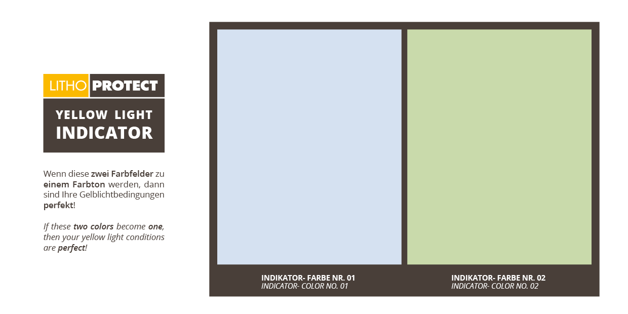
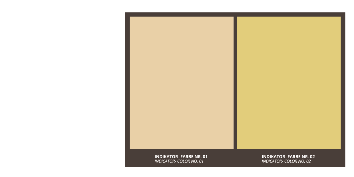
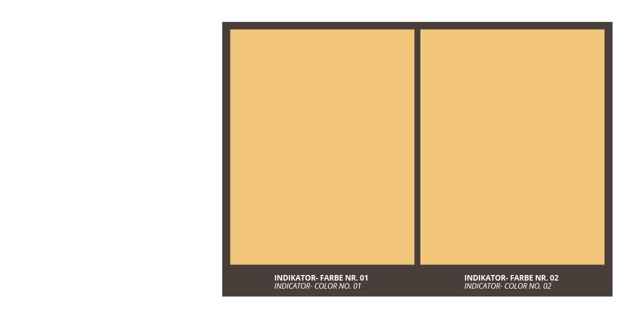
RAPID TEST FOR SUFFICIENT YELLOW LIGHT CONDITIONS
We created a simple test if your yellow light conditions are sufficient or not. Please take our test card with you into your yellow light room and check if both indicator colors look similar. If you still see a difference, there may be a problem with your yellow light and you should consider to exchange your yellow light filters. W With this sample, you can cover a simple desktop lamp and switch it on in a dark room. Now you can compare the visible result of the Lithoprotect® Light with your current yellow room illumination, using the yellow light indicator.
Indicator Color under Lithoprotect® yellow light:
Even with solely i-line (365 nm) resists, there is a residual sensitivity to blue light, which can be critical in the case of cross-linking negative resists or chemically amplified, correspondingly highly sensitive positive resists.
Therefore, not only the UV fraction of solar or blue sky light but also white artificial light from, for example, white fluorescent tubes can expose photoresist unintentionally if no suitable shielding is applied by means of suited filters with a sufficiently strong absorption for wavelengths below ≈ 520 nm.
We would be pleased to provide you our yellow light indicator and a free sample of our Lithoprotect® yellow foil for this rapid test!
04
OUR RANGE
OPTICAL TRANSMISSION
The optical transmission properties of the UV-protection yellow foil Y520 were specially designed for the high quality standards in the field of yellow rooms (photolithography in microelectronics manufacturing). The graph below is semi- logarithmic.
In a linear plot of the same filter you see only zero values because you cannot distinguish between 0.1 or 0.0001%. If you compare our foil with other foils, be sure to ask for a semi-logarithmic plot of the transmission since these differences cannot be seen in a linear plot.
INSTALLATION
The
Lithoprotect® yellow foil Y520
can be processed comparable to paper. You can use double-sided adhesive tape for mounting it on windows, privacy screens, room dividers, lamps and front openings.
However, we recommend to use for large windows applications our self-adhesive
Lithoprotect® yellow foil YSA520. The
Lithoprotect® yellow foil YSA520
can be glued easily and bubble-free with our
Lithoprotect®
mounting fluid DXMF301 on any smooth and solid surfaces.
Detailed information is available in our assembly instructions for self-adhesive
Lithoprotect® yellow foil YSA520
.
For filtering fluorescent tubes, we recommend our specially designed polycarbonate sleeves. Here, our UV protective yellow film Y520 is already incorporated, so you can cost-effectively “upgrade” standard white fluorescent tubes for your yellow light application.